Fabrication Friday

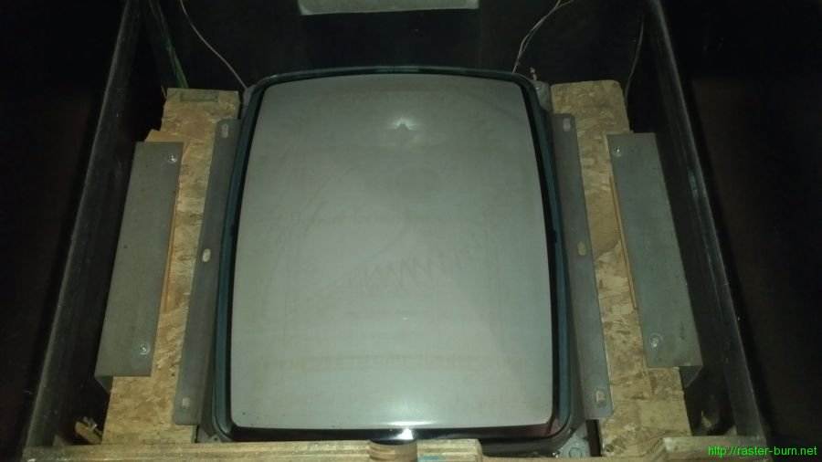
So I’ve had a Midway Bosconian cabinet for a while that I acquired converted to Krazy Bowl, and then swapped in Capcom Bowling myself. Part of that initial conversion, performed long ago by an operator, was to switch the game from Bosconian’s horizontal monitor orientation to the vertical orientation required for Krazy Bowl. This was done using very questionable materials, with results that looked like this…

Scraps of OSB, a stack of shims, and drywall screws isn’t how *I* would have done it… So I replaced all that with something sturdier. While structurally sound that still left one staring at the guts of the machine while playing it. And, because this was never a configuration supported by the cabinet originally, no premade bezels would fit the thing since the monitor was now mounted several inches higher than usual to allow for the tube neck to clear the back of the cabinet.

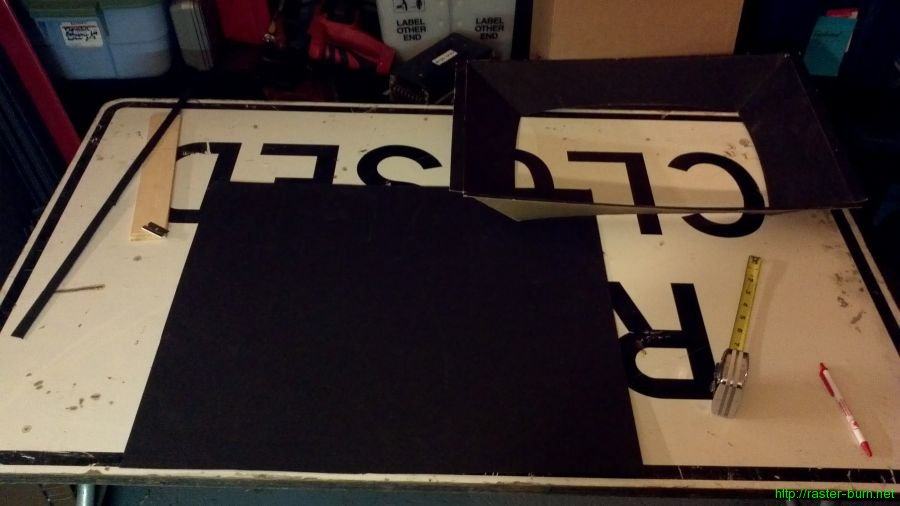
So I got a sheet of mat board and a used cardboard bezel from my parts stash and got to work…

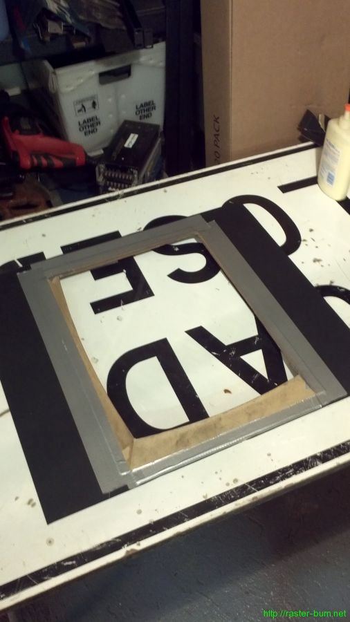
First step was straightforward: Cut the mat board down and make a hole for the monitor.

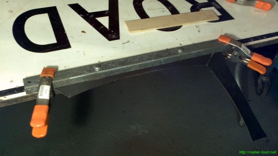
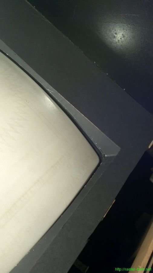
The next part took a little more craftiness. I measured the distance between the tube surface and the bottom of the mat board to determine how much clearance I had. It ended up being about a half inch at the middle of the tube’s curve along the long side. Then I measured from the new crease point in the bezel to the edge of the material to figure out how much excess I had, and trimmed it down allowing for about three quarters of an inch of material to glue to the mat board and hold the important part in place. Trimmed everything and then used a makeshift brake to make the new crease.

Test fit the one half of the bezel to make sure everything looked good, then cut down and creased the other half.

Then spent some time with it loosely taped together to adjust and get the tube centered in the new bezel. After getting it looking decent I glued down and taped the flaps to the mat board, and at the corners where the two halves of the curved bezel part come together.

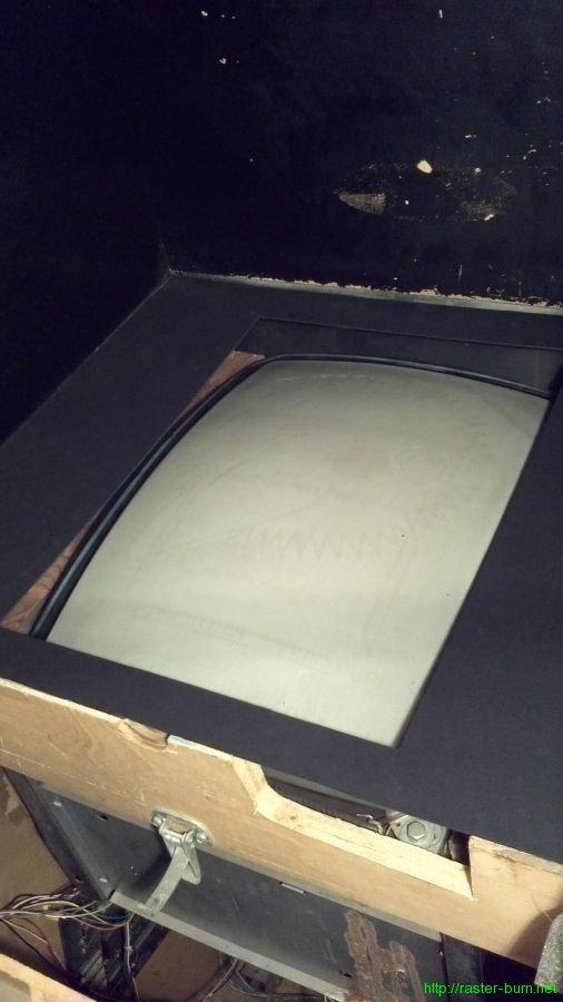
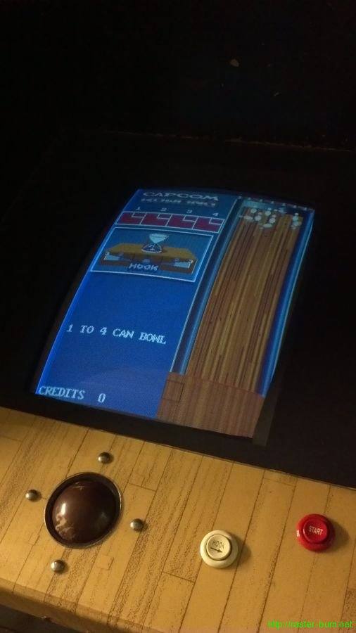
…And installed!

SNK Neo Geo NEO-MVH six slot board repair

Just finished the arduous task of replacing all the capacitors on the board out of my office’s SNK Neo Geo MVS-6-25 cabinet. It’s a monster, roughly 16″x20″ and two boards stacked one on top of another. The top board is identified as NEO-MVH SLOT6, while the bottom is labeled with NEO-MVH MV6.

This monster board has a monster cap list, with a total of 39 capacitors required to totally fill it out. Thankfully they’re all labeled on board with which values go where (though voltages are NOT labeled so keep track!) The condensed list of everything I had to order is as follows:

3x  1.0μF  50v
12x 4.7μF  25v
2x  4.7μF  50v
1x  10μF   16v
3x  22μF   16v
1x  22μF   50v
1x  47μF   16v
5x  100μF  50v
2x  220μF  16v
1x  220μF  35v
6x  470μF  16v
2x  1000μF 16v

I didn’t follow my advice and failed to note what exact voltages went where, but kinda felt it out based on the quantities and locations… Risky, but it worked. I fired the board up to test and the newly potent audio circuits startled the hell out of me since I’d left the volume slider at close to maximum from its previous weakened state.

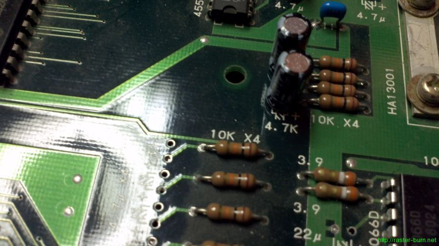
While working it over I noticed that a few caps have incorrect labels screened on the board. In particular there’s a pair of 4.7μF caps with 4.7K screened at their position as though they were resistors.

Also ran a set of leads from the old battery location so I can locate a new rechargeable battery offboard once I source one.

Monitor Meltdown

Spent this week straining my back moving CRT monitors like it was the 90s again.

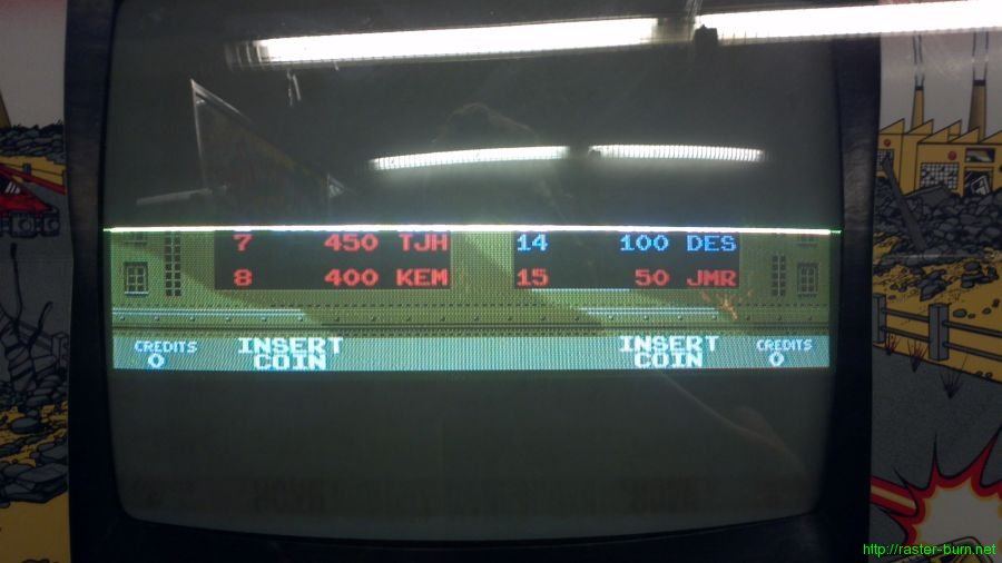
First was revisiting an Electrohome G07 that developed an exciting new failure after I recapped it and replaced the flyback transformer a few months ago. It would just energize but not show any picture. I checked the horizontal output transistor first since it hadn’t been replaced and they’re a common failure point. It was in fact blown so I threw a new one in, which yielded this…

It’s a start, but we need more than a quarter of the picture. I started by checking transistors X401 and X402, which metered fine. Then, worked my way through the resistors in the 400s and everything was within tolerances there. Then I reflowed some dubious traces and all the header pins. Still nothing after all that effort, which left me a bit stumped.

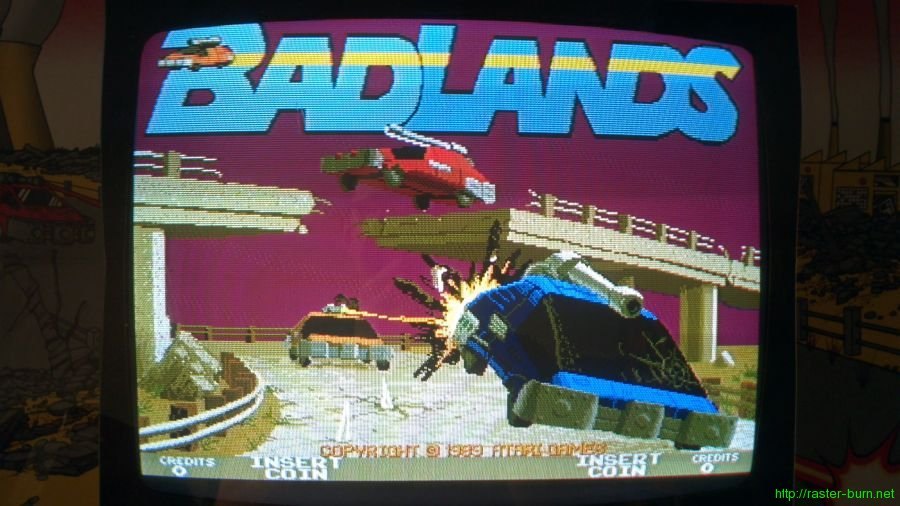
I decided to swap out X401 and X402 just because, and after swapping X402 got a screenful of Badlands again. So! Lesson learned, testing a transistor with a DMM doesn’t necessarily tell the whole story.

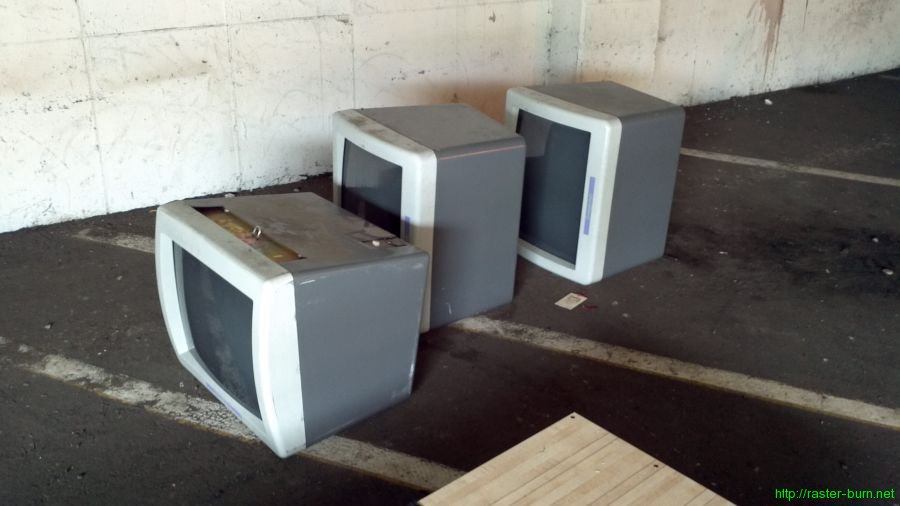
Second part of the CRT adventuring comes from the basement of one of Portland’s late bowling alleys. Hollywood Bowl closed recently after over 50 years, another casualty of the explosive redevelopment of NE Portland. Earlier this year there’d been some rumors, but they’d insisted their lease was intact for a long time to come and they had no intention of shutting up shop. Apparently someone threw enough money at the situation to break through and now we’re losing one of Portland proper’s last bowling alleys to make way for… A hardware store. What a waste.

My disappointment with that turn of events didn’t prevent me from touching down on the site like a starved vulture when it came time for the fixtures to be auctioned off. This past Wednesday I secured a few banks of Brunswick lockers, the big lighted ‘Entrance’ sign from the parking garage, and a few other small things. While I was there I noticed a big pile of overhead monitors in a corner of the garage that had been on the auction catalog initially but were pulled… I inquired about them and was told they were destined for the dump. Sooooo I did what any self-respecting scrounger would do and loaded a few up while retrieving the stuff I bought.

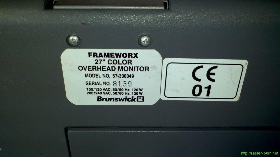
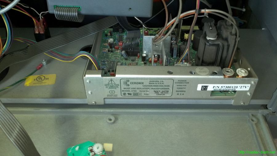
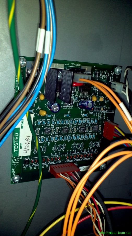
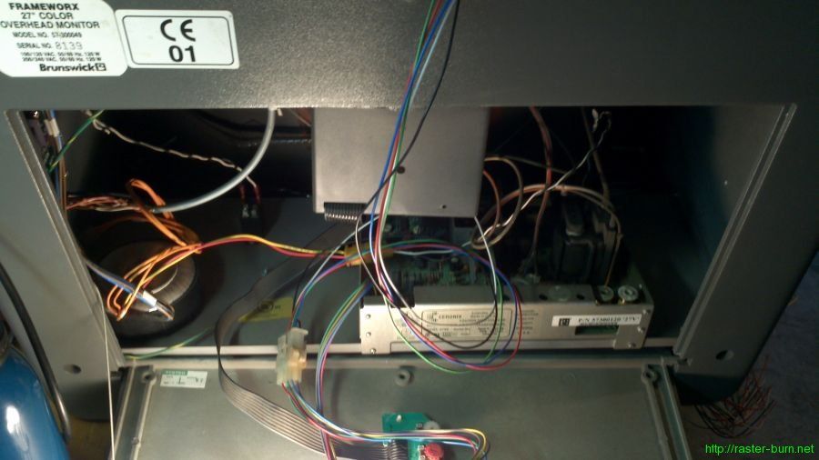
They’re Brunswick Frameworx system 27″ overhead displays, designed to be hung over the approach area of the bowling lanes and display scores and those dopey animations that play when you get a strike. The guts are a Ceronix model 2793 chassis and a little Brunswick board that gets fed off the 36V output from the isolation transformer and does some conversion of the signal from the scoring system, as well as controlling power to the monitor via a relay.

The Ceronix chassis is a standard CGA deal and it didn’t take a whole lot of modification to get the thing displaying the image from an arcade board.

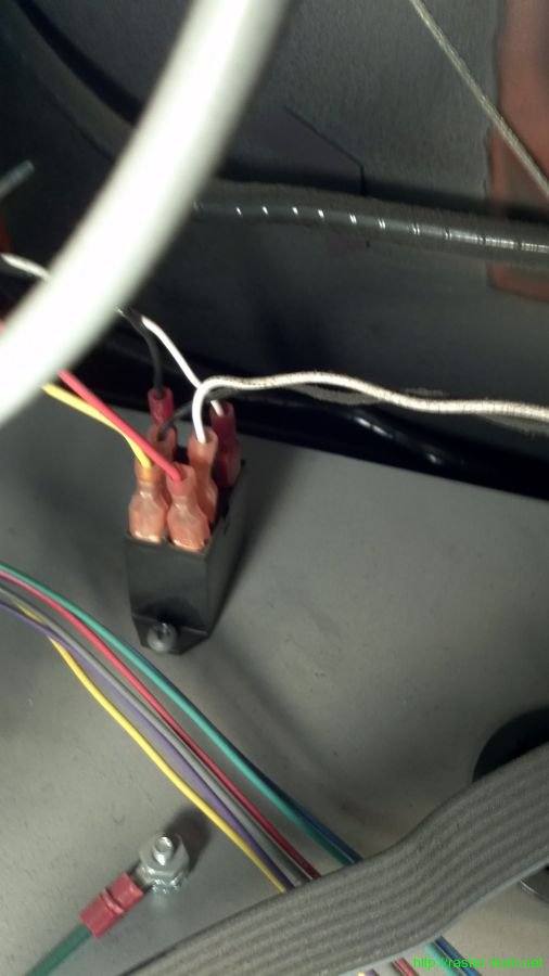
I had to bypass the Brunswick board by removing its 36V power connection, and bypassing the monitor power relay and connecting the AC output from the isolation transformer to the Ceronix power input directly.

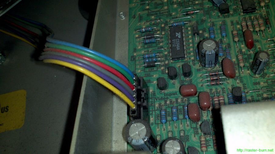
Then I took the video input harness that goes between the Brunswick board and Ceronix chassis, clipped off the Brunswick end, and fitted a Molex connector to mate it to an arcade wiring harness.

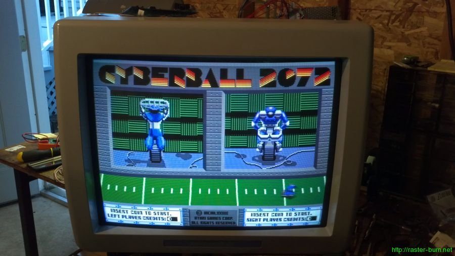
Hooked up my Cyberball 2072 board to test and dial in the adjustments.

Not too shabby for a freebie!

There is a service bulletin from Brunswick regarding these monitors, and the Ceronix chassis in particular. From reading old threads on Bowltech it looks like these chassis were prone to a manufacturing issue that led to weak or absent solder traces. Repairable, but definitely worth being aware of. It’s also likely that most or all of these things still in service will have had the defective components repaired or replaced by now.