Danger Zone – Williams F-14 Tomcat playfield swap

I checked off another project that’s been a long time in coming with this one. This particular F-14 Tomcat is another of the machines I grew up around at my parents’ shop in Anchorage. I always wanted to get it working but didn’t have the skills, or enough information to build them, back then. As I got into working on these machines in earnest after my move to Portland, it became another project that followed me down here to join Sorcerer and 300.

Even then, it sat for quite some time. Like most of the production run for this title, it suffered from extensive damage due to playfield inserts lifting out of place. It also had mylar installed over many areas of the playfield when new, which had now been pulled up by the rising inserts and taken up art with it. The pictures below are the state I found it in after over a decade in storage.

While the playfield was rough, the machine had been stored dry. It also didn’t look to have all that many plays on it before it had been laid up in storage. The boards were pretty clean, with no battery leakage, and all of the playfield mechanisms were pretty fresh looking, if dusty.

Some time after I took possession of the machine, Buthamburg (AKA Perfect Playfields) announced they would be doing a run of reproduction playfields for F-14 on Pinside. I got myself on the waiting list and after a few months a package from Germany arrived at my office.

Several months of procrastination later (I’d claim it was to let the clearcoat cure, but I’d be lying) I cracked things open and got the old playfield and new laid out side by side.

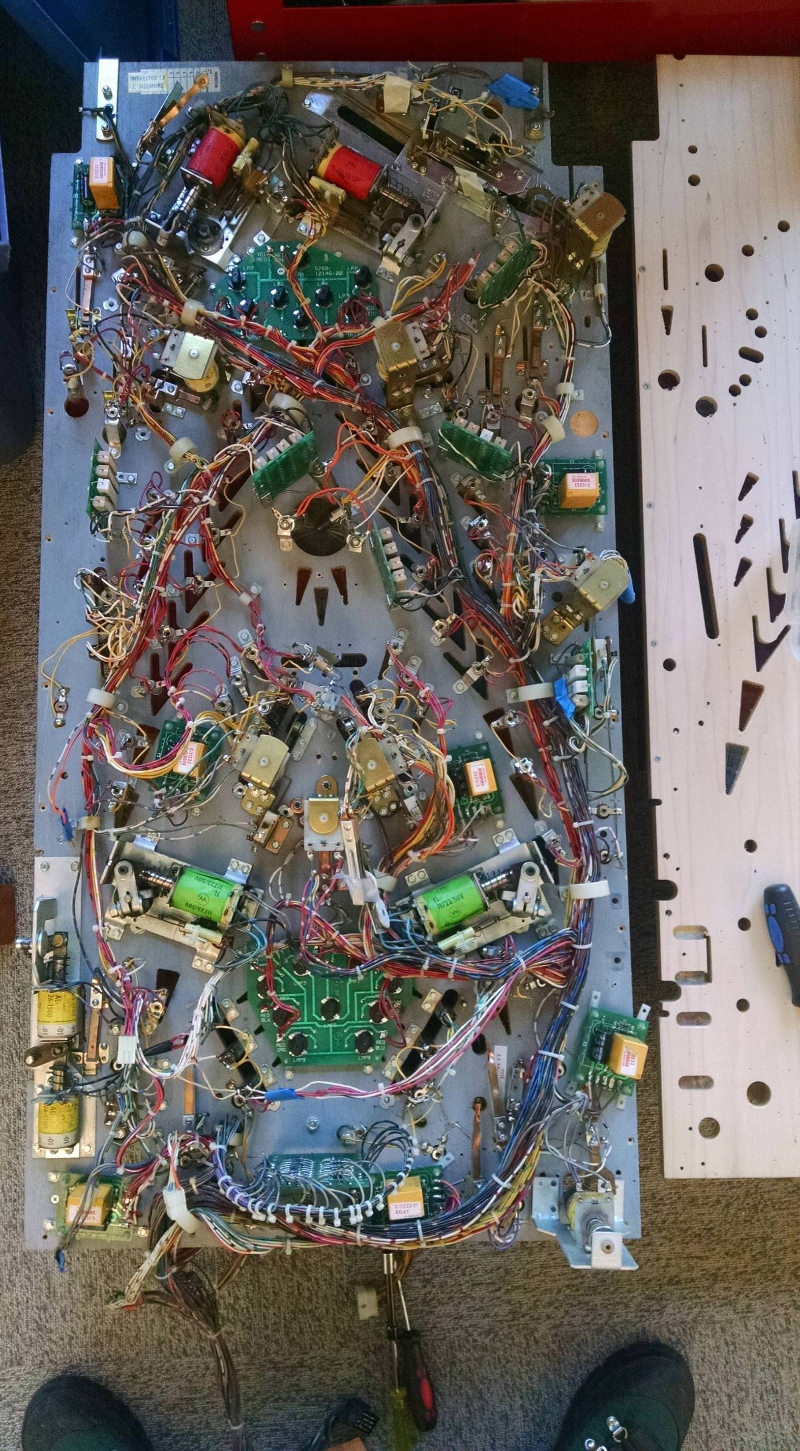
Disassembly was pretty straightforward. I took pictures of everything I could think to and still ended up with missing information. Next time I plan to take a few slow pan videos over the entire thing to get a more complete documentation of part placement and wire routing. The full gallery of pre-disassembly pictures can be found below (right click and open in new tab to view full resolution).

It took a while but I eventually got everything swapped over… While I kept the original incandescent flashers, I swapped all of the smaller bulbs over to warm white frosted non-ghosting LEDs from pinballbulbs.com, with a couple colored ones for the spots where an incandescent bulb would have had a color gel sleeve over it. I’ve been very satisfied with the results, though I’ve heard sunlight spectrum LEDs offer an even closer look to the original incandescent glow and plan to try them out on my next shop out.

A few things I did to ease the process and improve the end result were:

  • Tracing brackets of each assembly before removal to record their orientation
  • Replacing wood screw posts with machine screw posts mounted to new T-nuts from the underside for high impact areas, where possible
  • Didn’t trust the dimpling on the new playfield. While it was close, each of these machines is hand assembled, and it came down to using my eyes on the top of the playfield while making adjustments to get the proper fit for many of the mechanisms
  • Acquired some new drill bits and a nice set of pin vises for doing holes in the top of the playfield for things like wire guides

There were only two major issues I encountered after re-assembly.

The first was due to my decision to re-install the factory ground braid for several segments of the lighting. I picked up an electric staple gun to re-install it on the new playfield and found it did not have enough strength to drive the staples into the hard plywood. Worse than that though, was I ended up not being careful enough with the staples holding in the lamp sockets, and ended up with a few cases where a staple leg created a short to the barrel of the socket, resulting in blown GI fuses.

After that experience I wouldn’t re-use the braid again, nor use staples to install the sockets. Instead the next swap will include switching to the piggy back grounding with insulated wire used in other areas of the machine. Were I doing a detailed restoration where using factory style braid was non-optional, I’d find a pneumatic staple gun to do the job with less frustration. Regardless of the fasteners used, I’ll also be careful to continuity test a bit more extensively prior to first power up.

The second issue was a mysterious and very consistent air ball problem on ball launch. When you’d plunge a ball it would come flying out of the shooter lane and smack the glass much of the time, and even if it got going up the ramp would often not have enough velocity to make the orbit and enter play. I initially thought this was a wireform ramp alignment issue, and spent too long chasing that red herring… Ultimately though, it ended up being a problem of the alignment of the plunger assembly itself.

You can see in the above picture the outline of the assembly’s placement with the original playfield, and just how far I had to move it over to get the plunger centered with the lane of the new playfield. Following that adjustment, my air ball problems went away entirely.

It’s now half a year, several thousand plays, and a visit to the Portland Retro Gaming Expo later, and so far the machine has played beautifully and largely problem free after the initial shakedown period. Besides the issues noted above all I’ve had to deal with has been an occasional playfield element connection broken due to fatigue. I have seen the development of the dimpling due to ball impacts that is common to new clear coated playfields. I won’t be worrying about it too much as the game plays quite smoothly and I haven’t seen any actual finish loss, only what I’d consider normal wear, but it’s worth noting for those it bothers.

You can view the rest of the post-swap pictures of the machine below (right click and open in new tab to view full resolution). A thread full of others’ experiences with swapping in this particular run of reproduction playfields can also be found on Pinside here.

Between The Buttons

Caught a few interesting pieces this past weekend. Loading them out of a hundred degree warehouse wasn’t a treat, but it was worth the effort.

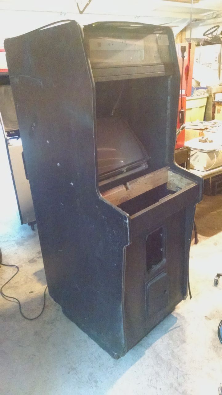
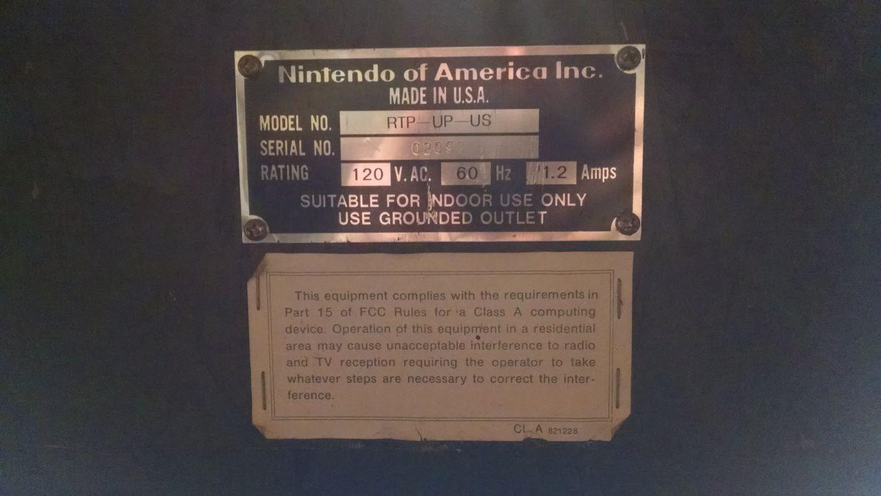
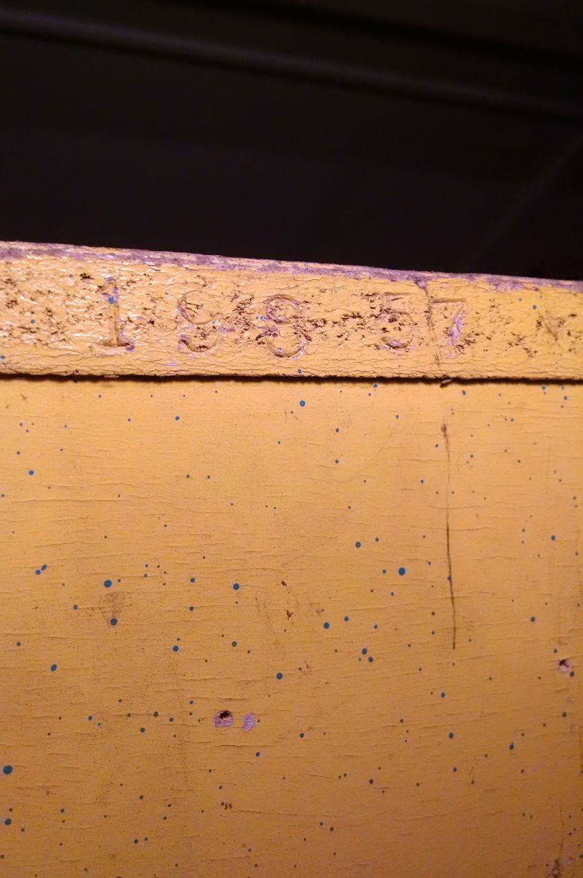
First is what started as a dedicated Nintendo R-Type upright. Serial number is quite low, but it wasn’t exactly a common game either.

At some point it received a conversion to Golden Axe 2 that looks a lot messier than it is. The wiring was all terminated nicely so I can clip a Nintendo harness right back into place on the original connectors that were left intact. The coin door and vault were pretty messed up or absent but I’ve got spares I salvaged from some destroyed cabs at another warehouse years ago that will be a good match.

With some cleaning and the installation of a few parts it’s already looking most of the way there.


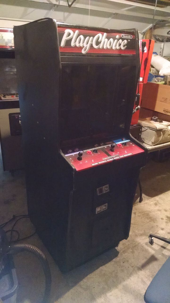
The second grab is another example of the purpose designed conversion kits that many manufacturers put out for the ubiquitous Pac Man and Ms Pac Man as they got on in years and stopped earning once the fever around those titles broke.

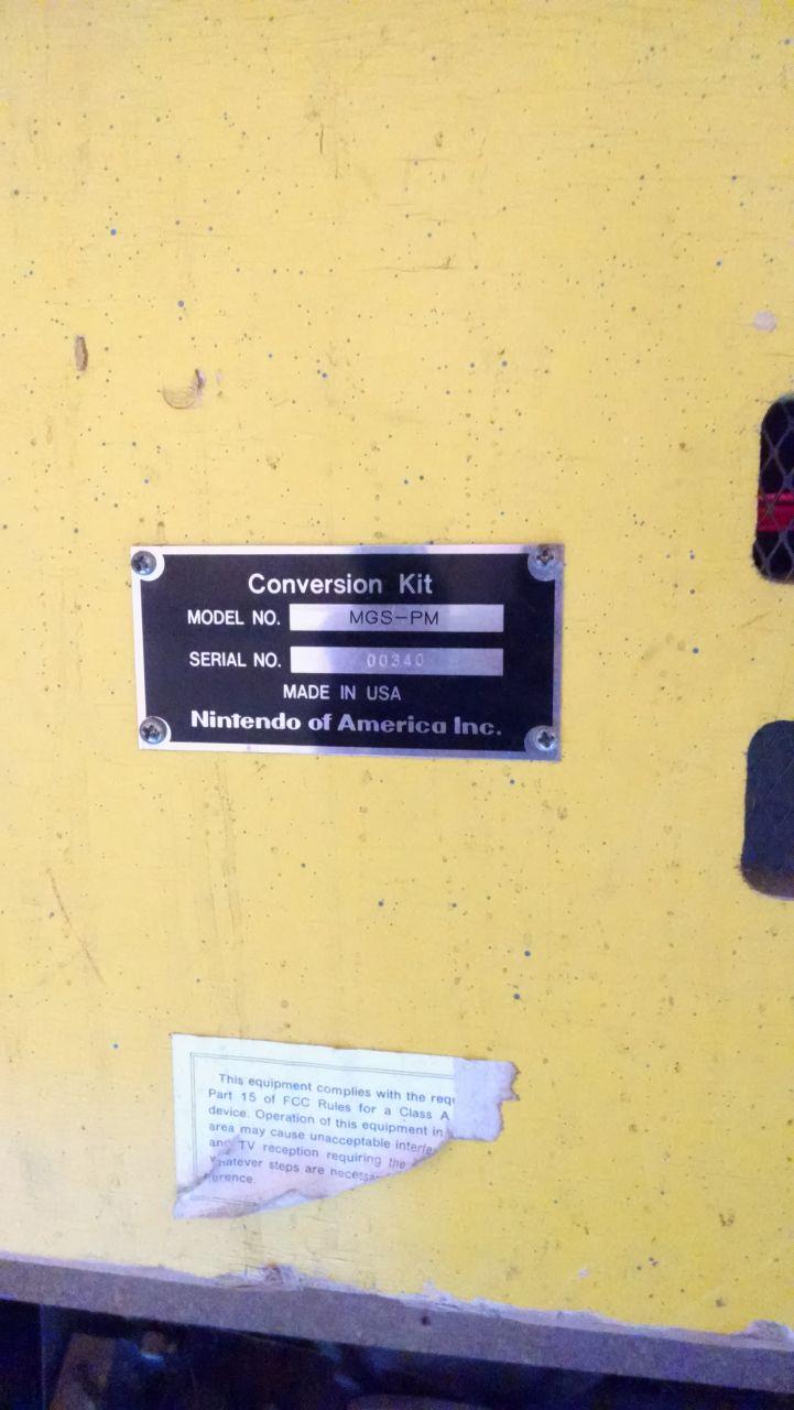
It’s a Nintendo conversion kit for the Vs. multi-game system. Similar in character to the Bally Sente conversion kit for these cabs, it takes a different approach to reconfiguring the monitor orientation and changing out the control panel.

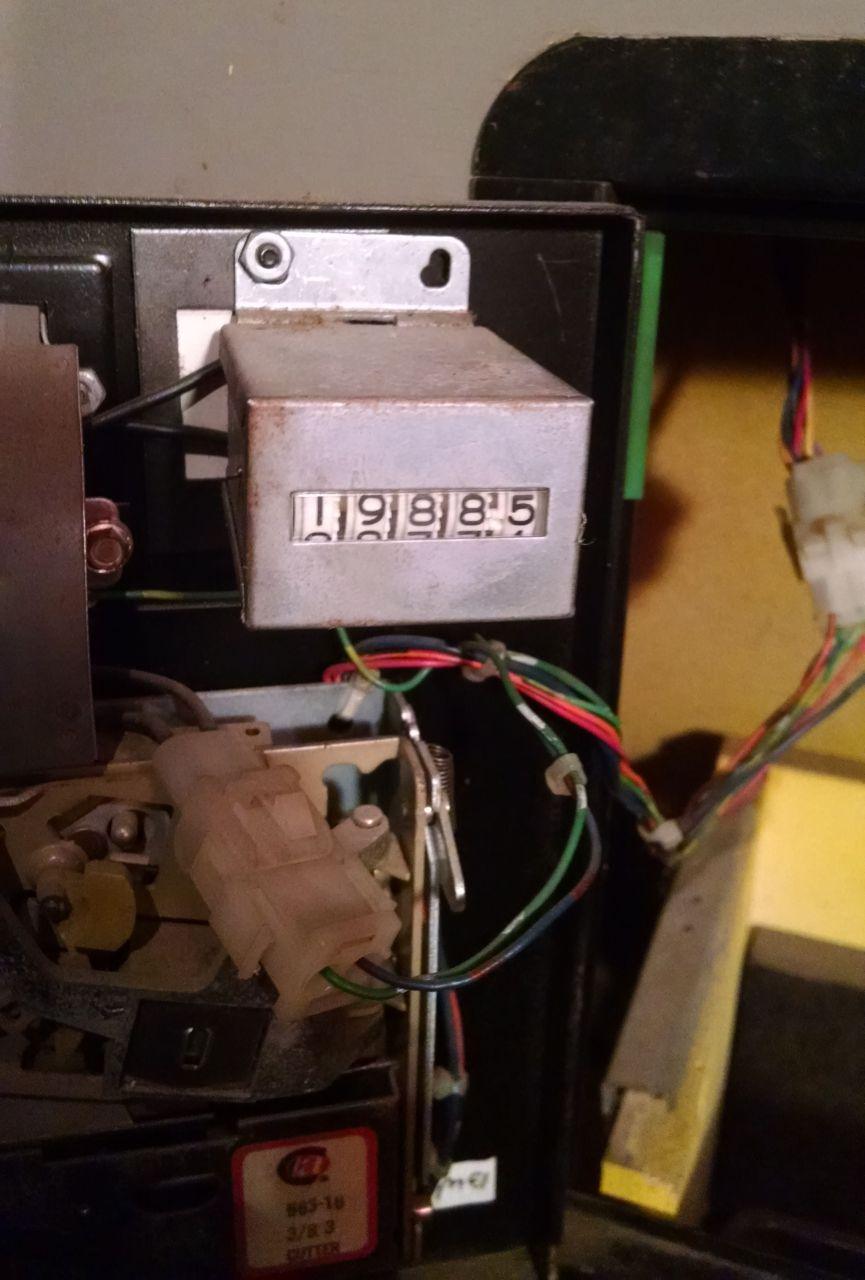
This one clearly earned its keep as Pac Man before the transformation with almost twenty thousand plays on the clock, likely paying for itself twice over in its original incarnation.

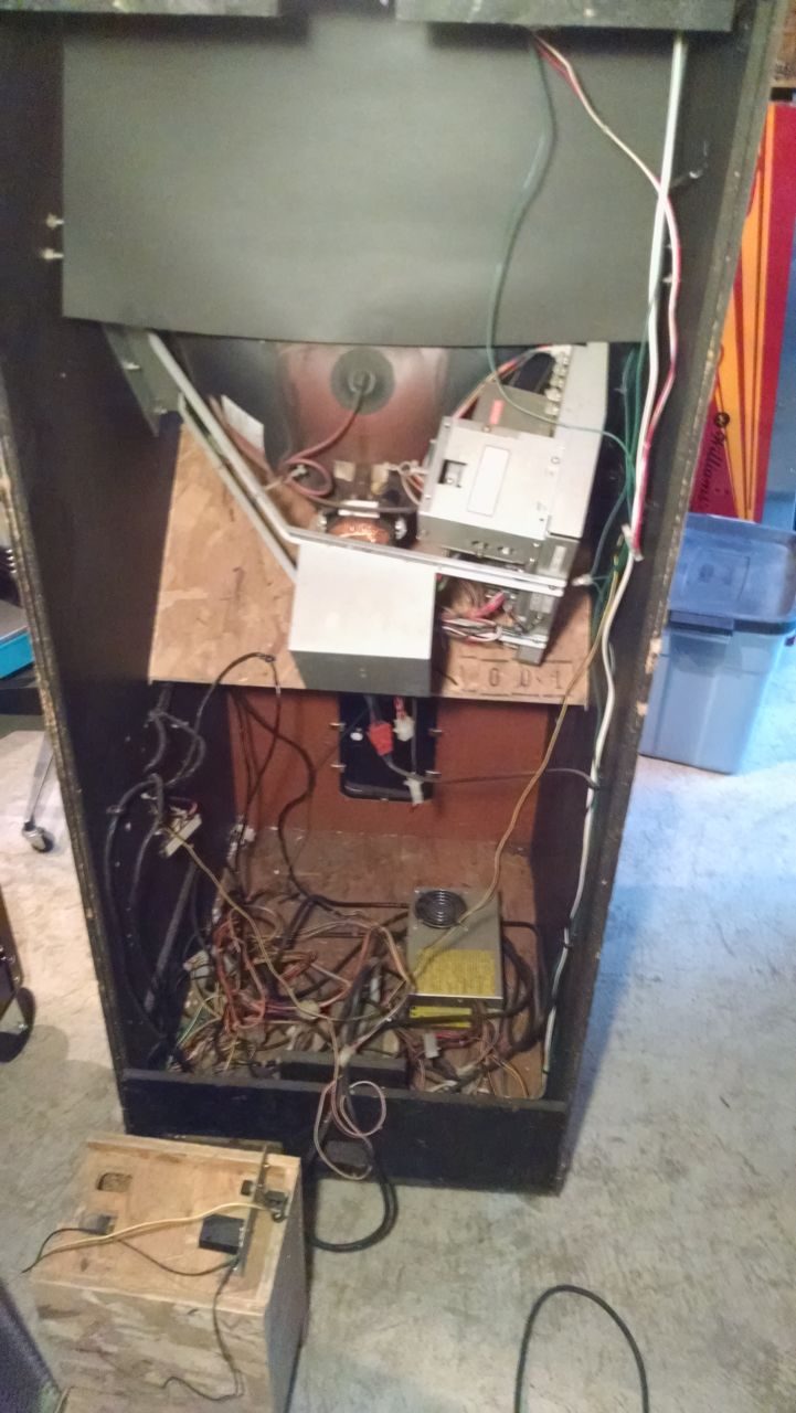
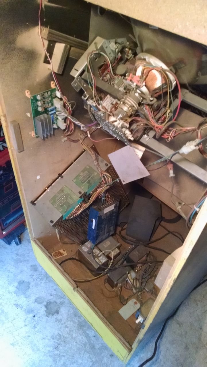
The conversion was quite cleanly executed, though the Nintendo switching power supply has at some point been swapped for a generic model which was left hanging against the PCB cage.

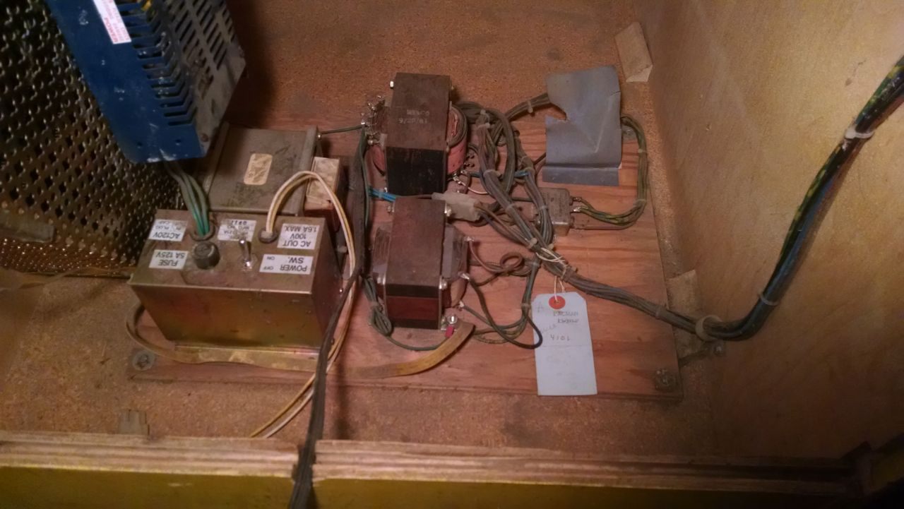
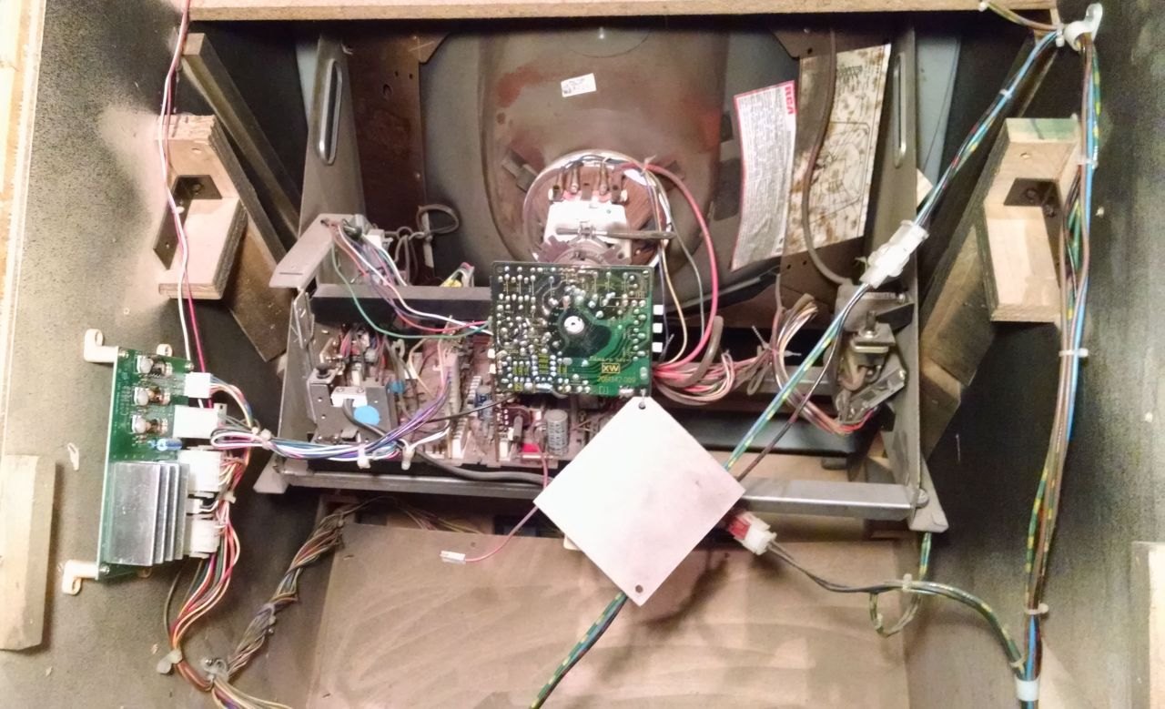
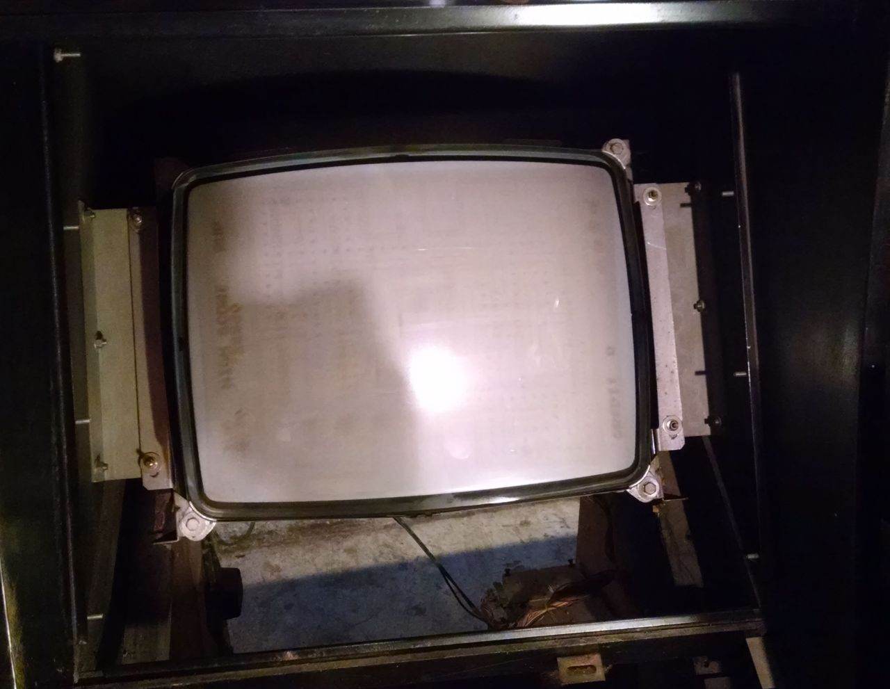
Not a lot is retained of the original Midway internals. Portions of the power panel, AC wiring, and the Wells Gardner K4600 monitor are all that came along for the ride. The monitor has the maze burn you’d expect from any Pac Man game but it’s hidden pretty well by the smoked plexiglass panel that goes in front. Interestingly a standard Nintendo isolation transformer was included with the kit, though its 100V output is left unused and the Midway transformer is used to isolate power to the monitor.

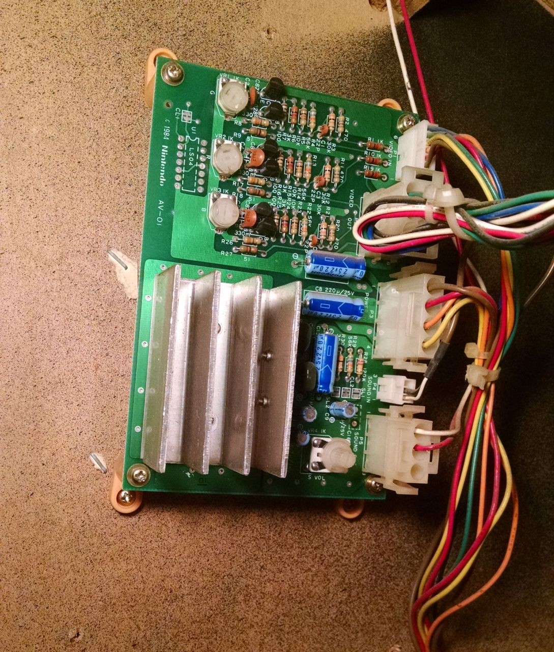
A Nintendo video inverter and sound amp board is used to adapt the signal from the Vs. PCB to the output hardware in the cabinet.

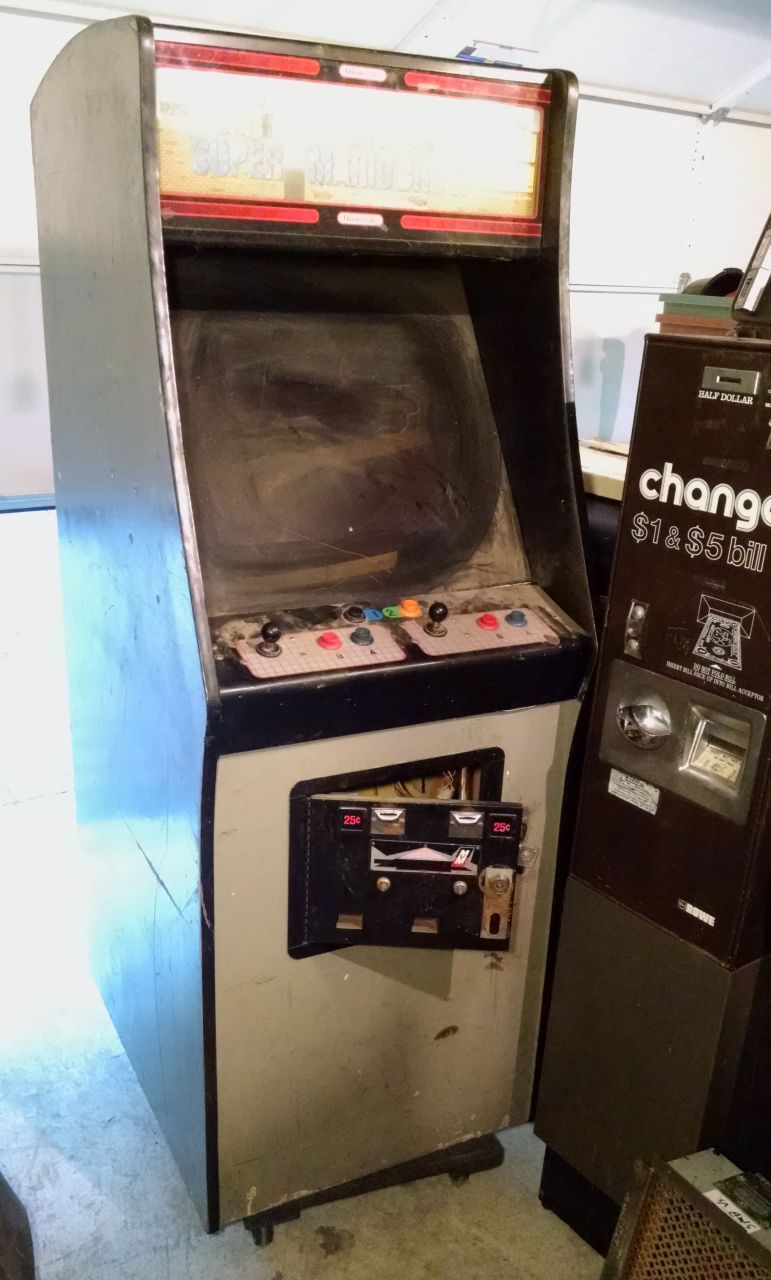
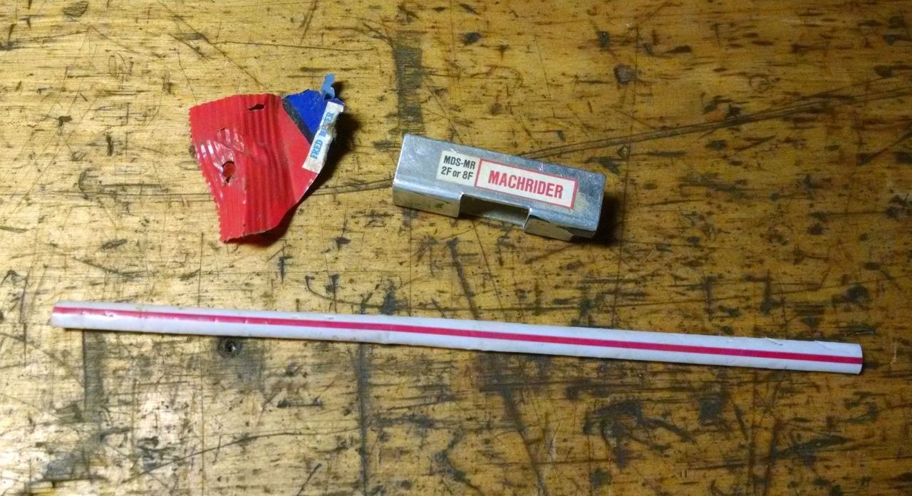
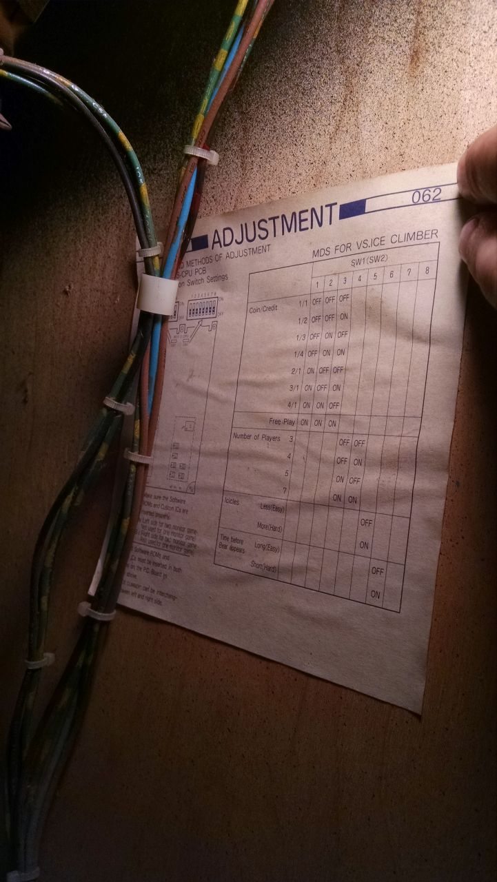
Detritus in the cab says this one hung around in the Pacific Northwest, nearby one of the outposts of the Fred Meyer chain. The straw trick (“It has been brought to our attention that a flattened straw or similar object can be passed through the center opening in the upper hinge. If the object makes contact with the coin switch, it can be used to run up multiple credits.”) to getting free credits on Nintendo games must have made the rounds too, though whoever applied it didn’t realize that it only works on original Nintendo coin doors. We can also see the Vs. boardset played host to a few different titles over time, with Ice Climbers and Mach Rider in evidence.

This one will stay converted, though I’ll swap in a Dr. Mario daughterboard for the Super Mario Bros. chipset.

Bait & Switch

The Atari Roadblasters I picked up is in good overall condition, and the major parts are working, but most of the controls have problems of one sort or another. The steering yoke was half disassembled when I picked the machine up, with a pile of parts rattling around in the coin box. A few of the trigger and thumb button switches had been replaced, with incorrect parts, and one of the actuator buttons and several screws were gone altogether.

I brokered a deal with another local collector and got my hands on a second mostly complete yoke and pedal assembly… I still needed the right switches though…

I knew I recognized the switches from somewhere… That somewhere turned out to be the mechanical switch keyboards all the nerds are going crazy for nowadays (self included). I happened to have such a thing lying around, one of the cheaper and more commonplace of its kind, a Dell AT101W.

This model comes populated with Alps black keyswitches of the non-clicky variety. The one I had was also fucking filthy. As a rule, if you haven’t personally cleaned a keyboard in the last year or so (and I mean really, complete disassembly involved, cleaned it) it probably looks like this inside. Thought you all might appreciate that knowledge…

The other side of that mess is a PCB like this, to which each of those keyswitches is soldered.

Some quality time with my desoldering pump later, I was able to peel the PCB away from the keyswitches and their mounting plate. If you desolder the connections well, they’ll come apart much like this. If you do it wrong, you’ll either get nowhere, or rip the guts out of all of the keyswitches. Don’t try to do this with wick or a manual pump, is all I can say.

Even exercising some care I ended up breaking a pin or two on several keyswitches. Seems like they’re fairly brittle. Even with some loss I still ended up with plenty for this project though.

Removing the switches from the mounting plate was tedious but straightforward. Each switch has four tabs that secure it to the plate. I used a steel ruler to push in one side of two tabs at a time. It took a while but I was able to remove all of the switches without damage.

Alright, this is what really matters… On the left is one of the Omron B3G-S keyswitches that came out of the yokes originally. On the right is one of the black Alps from the Dell keyboard. Below is the small PCB the switches mount too and ride on inside the yoke assembly.

We can see a few differences right off. For one, the Omron switches have three pins, while the Alps have only two. The extra pin on the Omrons doesn’t matter, it only comes into play if you want to use these switches in a normally closed configuration, which is not the case for the Atari yoke. The small PCB the switches will be installed on is set up for a variety of different pinouts, so the slight difference in alignment doesn’t matter either.

There are two differences that *do* matter though…

First, the Alps switches have slightly larger pins than the Omron ones. This was easy to handle by enlarging the holes on the PCB with an appropriately sized drill bit in a pin vise.

Second, the Alps switches have a different setup for mounting then the Omron switches, and the yoke body halves assume you’re using the Omron type. To get the Alps to fit I had to clip off the tabs, and file down the remaining plastic to match the profile of the Omron switches while retaining the rectangular protrusion that keeps the switches from being pushed down into the yoke assembly.

The above picture shows an Omron switch on the left, a modified Alps in the middle, and an unmodified Alps on the right. A small straight file is sufficient to mod the Alps switches to fit, they should end up around 14mm wide when all is said and done.

Here we can see one of the original Omron switches installed in the lower position with the white actuator pin, and a modified Alps switched installed in the upper position with a black actuator pin.

It’s a bit of work, but considering the high failure rate of the Omron switches, and the fact that used replacements start at six bucks each and only get higher from there, I found it to be worth the effort. A single mechanical switch keyboard should have me covered for several lifetimes as far as replacement switches for this style of yoke go, and I know this style of standard key switch is used in other games as well.

If you’re another Roadblasters owner coming upon this information be advised that this is only confirmed for the kit style Roadblasters yoke. The dedicated Roadblasters yoke is a different assembly entirely and may use different switches. If anyone has pictures of the internals of a dedicated style yoke, or information on the switches used therein, please send them to me and I’ll update the post to include that information.