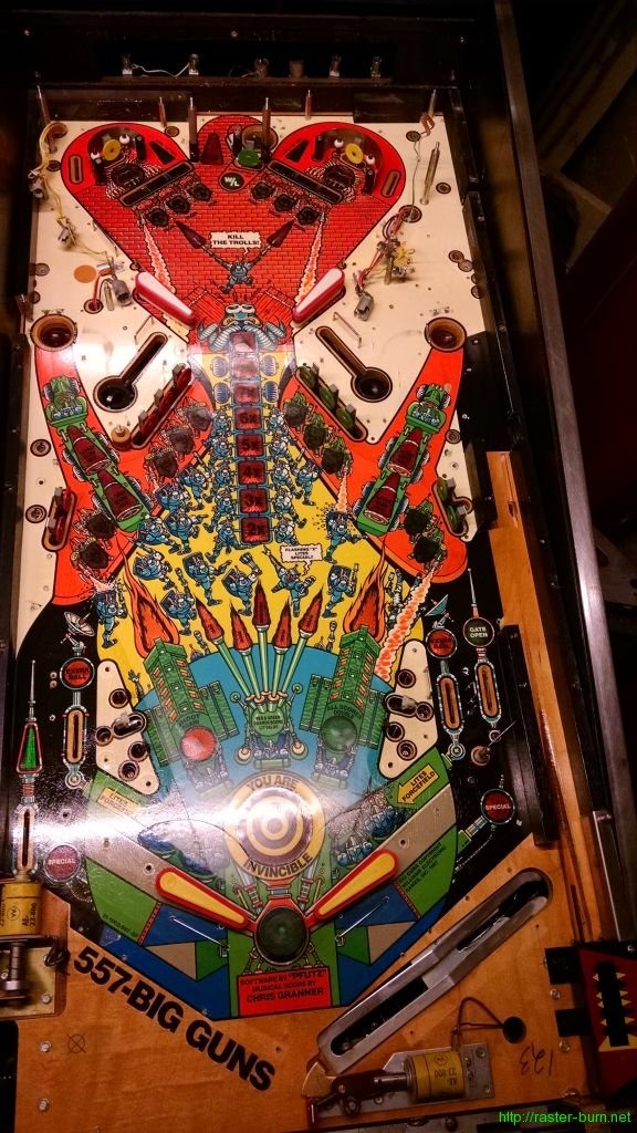
From this…
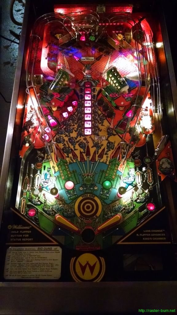
…to this…
…took about 3.5 hours over two sessions. Or, to put it in relative terms, about a third of the time I put into Sorcerer, and even more favorable compared to Comet… Though I can’t say exactly how much better since I didn’t keep time for that one. I’m very pleased with how streamlined my workflow is becoming. During disassembly I basically break the playfield into a 2×8 grid and work my way through each section, photograph it, remove parts in logical (to me, at least) groupings, and bag and label each subassembly.
I found that the most time consuming part of reassembly on the previous two tables was filling in the blanks where I hadn’t done enough documentation during teardown. Being extra methodical with breaking this one down saved me a ton of time in recomposing it, despite the significant increase in complexity from System 9 pins like Comet and Sorcerer to the more feature laden System 11 based Big Guns.
Given there are 2-4 layers of parts to remove to get to any given bulb, I wasn’t thrilled at the prospect of having to tear things down to get to short-lived incandescents, so I decided to go the LED route. I used Pinballbulbs.com non-ghosting LEDs in warm white for the #44 general illumination and cool white for the #89 flasher bulbs on the top of the playfield and in the area behind the ‘wall’ at the back.
I think the results look pretty nice. The photo makes it look like a lot of the plastics are blown out by the brightness of the LED bulbs but in person they have a nice bright, even light behind them that shows off the art and lights up the playfield nicely without being overpowering. After seeing how the top of the playfield looks I’m going to go forward with replacing the lamps under the inserts on the bottom of the playfield, and replace the lamps in the backbox as well. The previous owner installed a color ‘coordinated’ LED kit in the backbox and it makes the art look really bad, since the color of the LEDs completely overpowers the translite’s coloration.
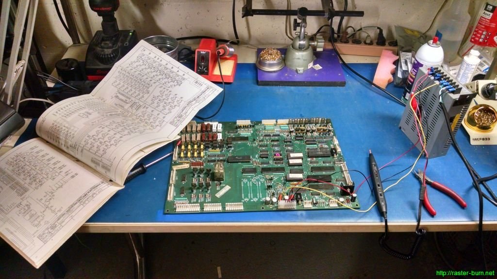
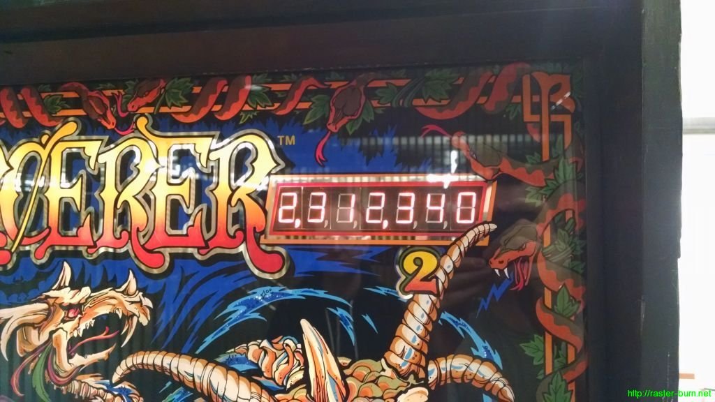
Now that Big Guns is back together I’m going to swap it in for Sorcerer at the office and bring that one into the shop for some MPU diagnosis… After having several hundred balls played through it without a hiccup during a party the company hosted I turned it on the day after and it was resetting randomly during gameplay. Poking around (very literally) narrowed the issue down to a bad connection or flaky component in the lower right corner of the MPU board, but tracing it further than that is more than I want to do with the limited tools I have at the office.
If you’re interested in seeing what the disassembly process looks like (or have one of these things you’re trying to piece together yourself), see the gallery below for all of the reference photos I took while tearing this thing down:


