Bait & Switch

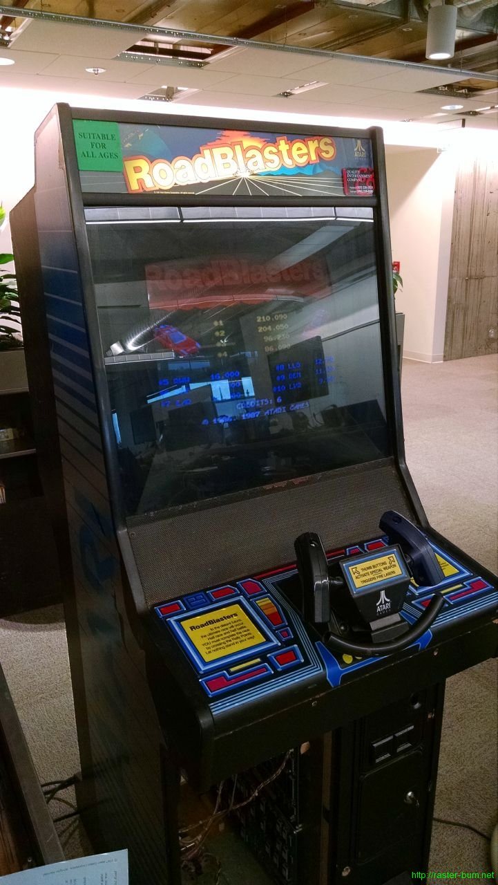
The Atari Roadblasters I picked up is in good overall condition, and the major parts are working, but most of the controls have problems of one sort or another. The steering yoke was half disassembled when I picked the machine up, with a pile of parts rattling around in the coin box. A few of the trigger and thumb button switches had been replaced, with incorrect parts, and one of the actuator buttons and several screws were gone altogether.

I brokered a deal with another local collector and got my hands on a second mostly complete yoke and pedal assembly… I still needed the right switches though…

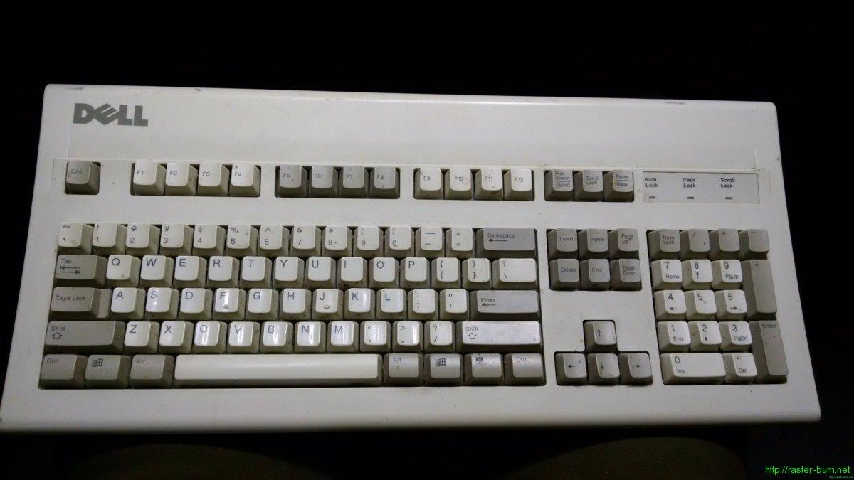
I knew I recognized the switches from somewhere… That somewhere turned out to be the mechanical switch keyboards all the nerds are going crazy for nowadays (self included). I happened to have such a thing lying around, one of the cheaper and more commonplace of its kind, a Dell AT101W.

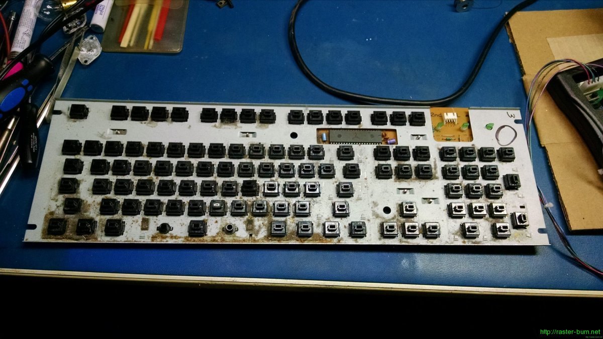
This model comes populated with Alps black keyswitches of the non-clicky variety. The one I had was also fucking filthy. As a rule, if you haven’t personally cleaned a keyboard in the last year or so (and I mean really, complete disassembly involved, cleaned it) it probably looks like this inside. Thought you all might appreciate that knowledge…

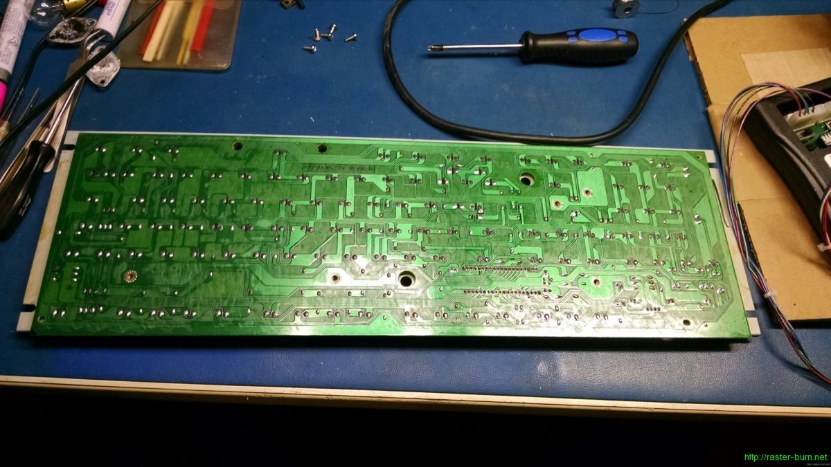
The other side of that mess is a PCB like this, to which each of those keyswitches is soldered.

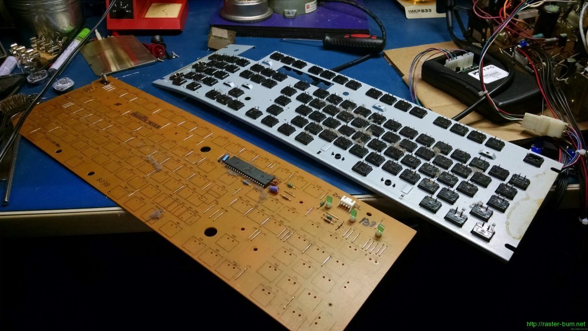
Some quality time with my desoldering pump later, I was able to peel the PCB away from the keyswitches and their mounting plate. If you desolder the connections well, they’ll come apart much like this. If you do it wrong, you’ll either get nowhere, or rip the guts out of all of the keyswitches. Don’t try to do this with wick or a manual pump, is all I can say.

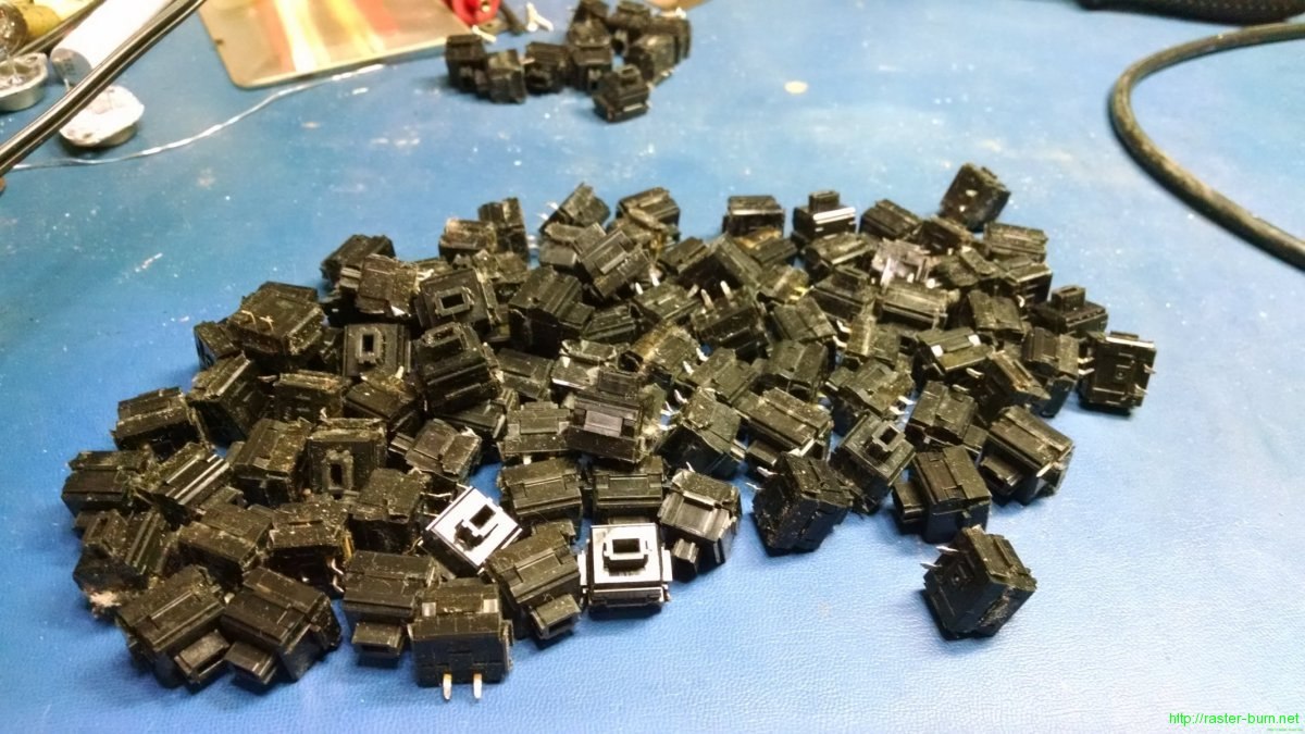
Even exercising some care I ended up breaking a pin or two on several keyswitches. Seems like they’re fairly brittle. Even with some loss I still ended up with plenty for this project though.

Removing the switches from the mounting plate was tedious but straightforward. Each switch has four tabs that secure it to the plate. I used a steel ruler to push in one side of two tabs at a time. It took a while but I was able to remove all of the switches without damage.

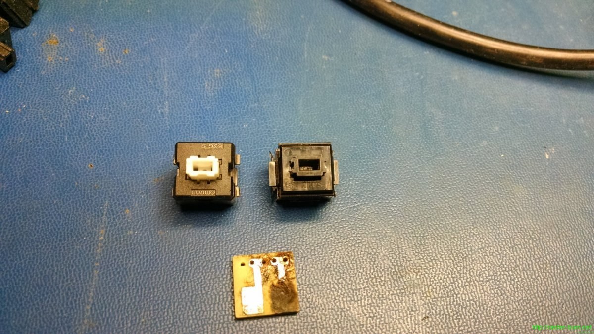
Alright, this is what really matters… On the left is one of the Omron B3G-S keyswitches that came out of the yokes originally. On the right is one of the black Alps from the Dell keyboard. Below is the small PCB the switches mount too and ride on inside the yoke assembly.

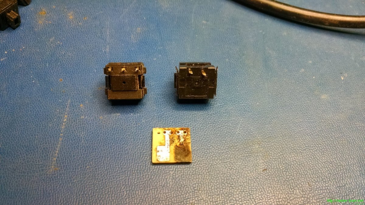
We can see a few differences right off. For one, the Omron switches have three pins, while the Alps have only two. The extra pin on the Omrons doesn’t matter, it only comes into play if you want to use these switches in a normally closed configuration, which is not the case for the Atari yoke. The small PCB the switches will be installed on is set up for a variety of different pinouts, so the slight difference in alignment doesn’t matter either.

There are two differences that *do* matter though…

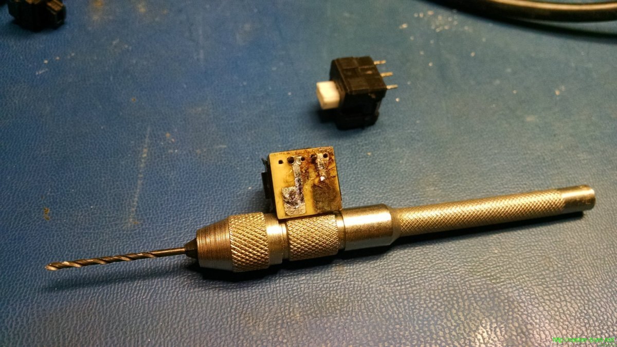
First, the Alps switches have slightly larger pins than the Omron ones. This was easy to handle by enlarging the holes on the PCB with an appropriately sized drill bit in a pin vise.

Second, the Alps switches have a different setup for mounting then the Omron switches, and the yoke body halves assume you’re using the Omron type. To get the Alps to fit I had to clip off the tabs, and file down the remaining plastic to match the profile of the Omron switches while retaining the rectangular protrusion that keeps the switches from being pushed down into the yoke assembly.

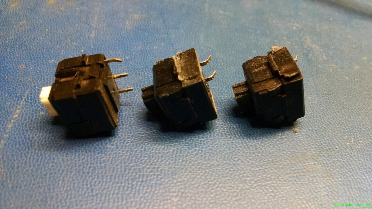
The above picture shows an Omron switch on the left, a modified Alps in the middle, and an unmodified Alps on the right. A small straight file is sufficient to mod the Alps switches to fit, they should end up around 14mm wide when all is said and done.

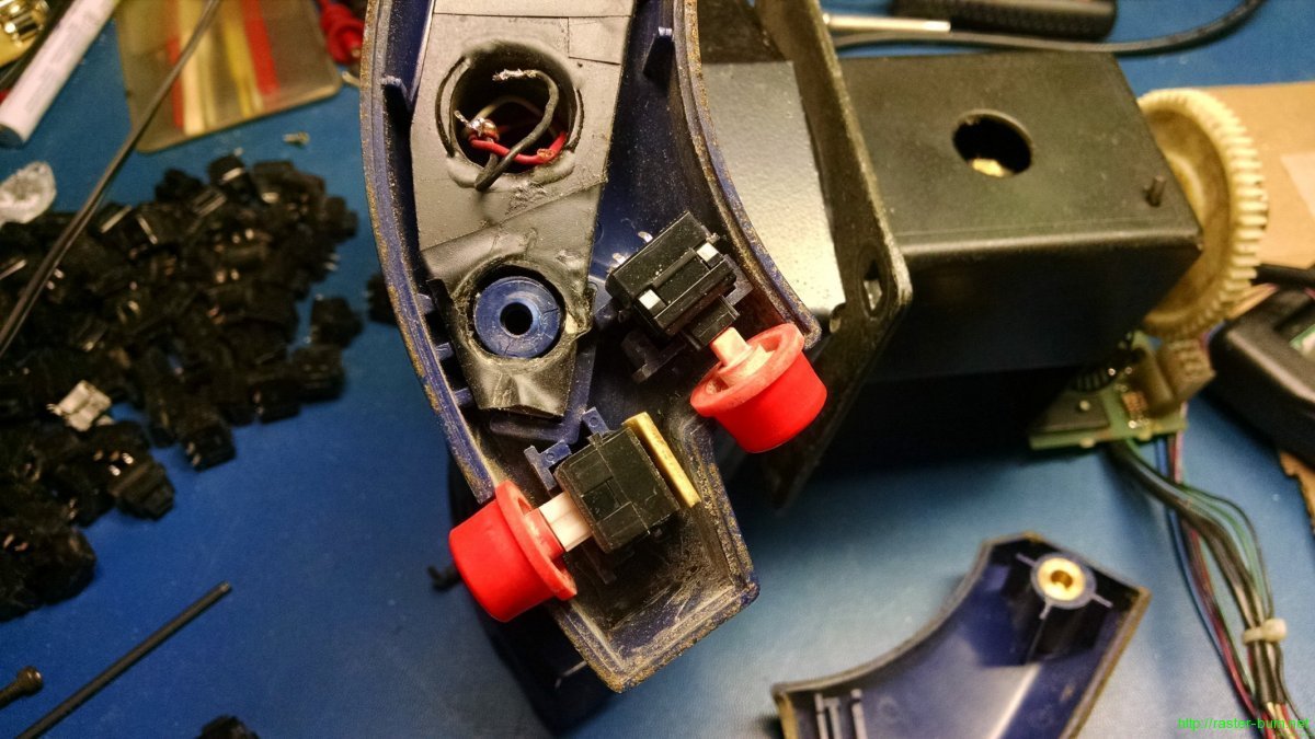
Here we can see one of the original Omron switches installed in the lower position with the white actuator pin, and a modified Alps switched installed in the upper position with a black actuator pin.

It’s a bit of work, but considering the high failure rate of the Omron switches, and the fact that used replacements start at six bucks each and only get higher from there, I found it to be worth the effort. A single mechanical switch keyboard should have me covered for several lifetimes as far as replacement switches for this style of yoke go, and I know this style of standard key switch is used in other games as well.

If you’re another Roadblasters owner coming upon this information be advised that this is only confirmed for the kit style Roadblasters yoke. The dedicated Roadblasters yoke is a different assembly entirely and may use different switches. If anyone has pictures of the internals of a dedicated style yoke, or information on the switches used therein, please send them to me and I’ll update the post to include that information.

Interstellar Safari

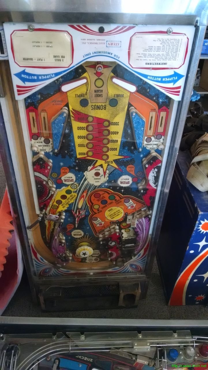
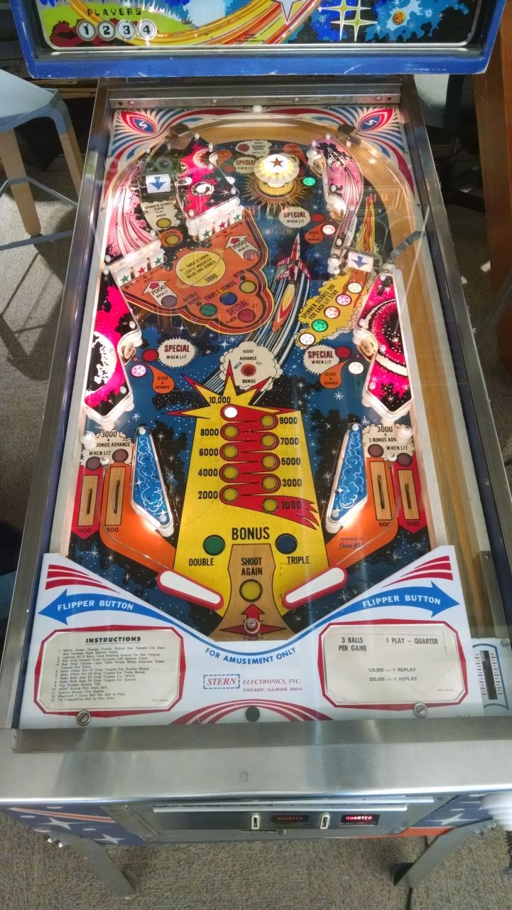
Took a little step back the timeline from prior projects with this last one. Designed in 1978, Stern Stars is part of the earliest wave of solid state machines, and bears many resemblances to its electromechanical predecessors. Most noticeably, it uses a chime box for its sound effects rather than a speaker.

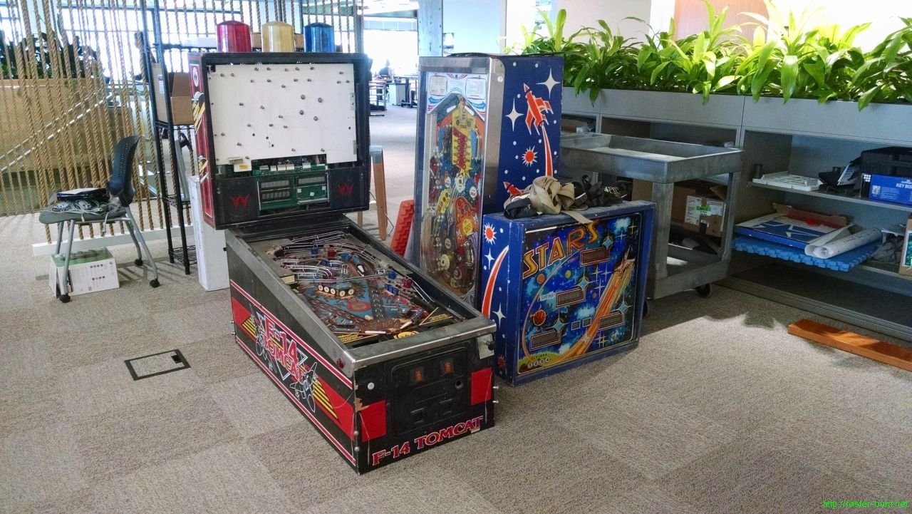
The example I have landed alongside F-14 Tomcat, both fresh out of very long hibernation.

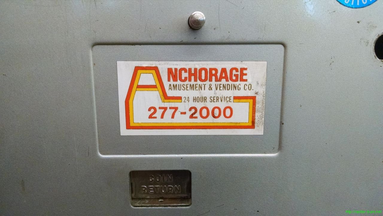
If the musty odor of long dead cigarettes didn’t give it away, the op tag confirms this machine spent some time on the bar circuit in Anchorage. While this machine survived its stint, the phone number for the Anchorage Amusement and Vending company now points to a physical therapist. Their last address of record is a still standing but one step above derelict warehouse with boxes and equipment piled high in front of the windows, and a high fence festooned with ‘No Trespassing’ signs.

While filthy, strung with rotten rubber, and malfunctioning, the bones of this Stars are quite good.

All that grodiness is probably the only thing that save the playfield from having a groove worn into it by the dragging right flipper, so I can’t complain too much about the mess.

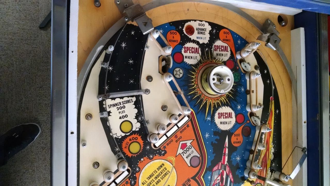
The flipper assemblies needed an almost complete rebuild, the only original parts left now are the frames underneath the playfield. For some reason Stern used aluminum for most of the metal parts on this machine, including the flipper shafts, and one was bent enough to cause the entire mechanism to bind.

I had to modify the bushings I received from Marco, despite them being labeled as appropriate for this machine, because they were too tall for the playfield. A few minutes with a saw fixed that right up though.

The drop targets were another area where the aluminum hardware caused problems. The arms the targets ride on had deformed around the pins that hold the mechanism together, causing them to mushroom out around the pin shafts and in the most extreme cases this would cause them to bind against other parts of the drop target assembly. I straightened everything as best I could and filed down the burrs caused by this wear. Now the mechanisms work, albeit a bit sloppier than from the factory since the holes are wallowed out and some material was lost in the process. The reproduction drop targets from Marco are slightly different in design from the broken originals, but the changes didn’t cause any fitment issues.

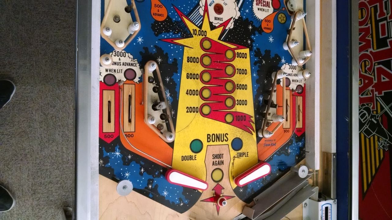
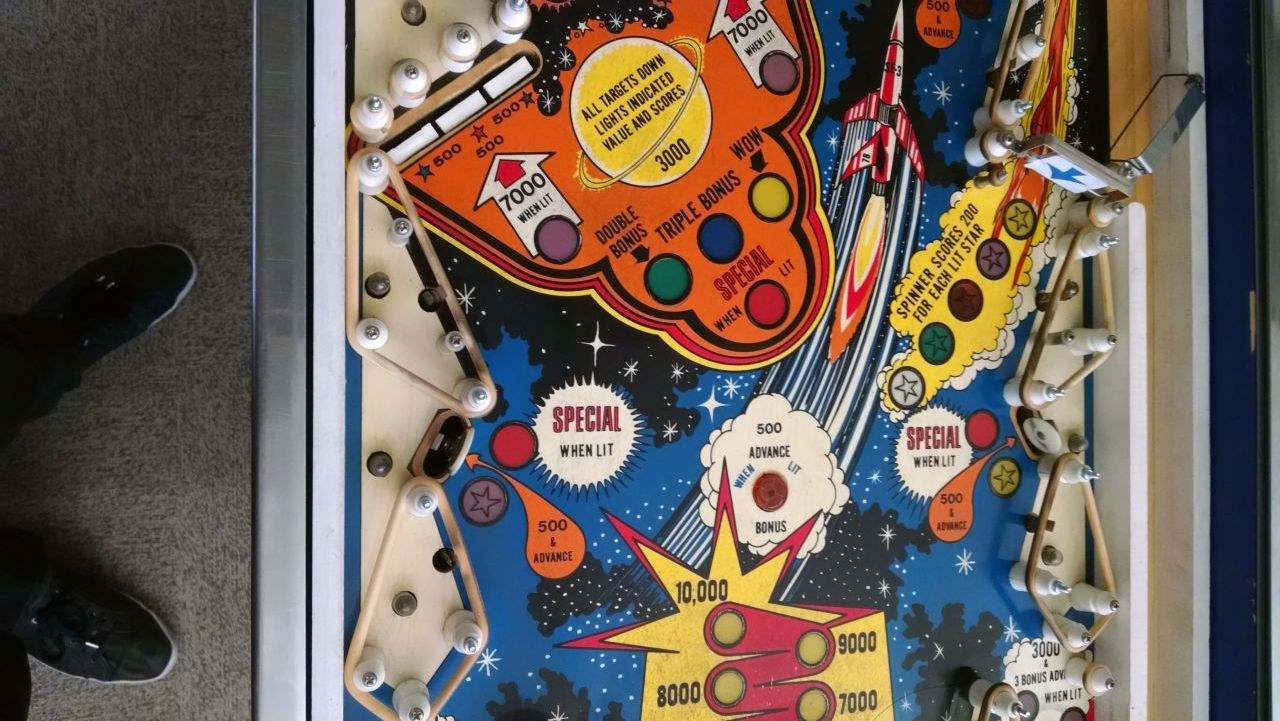
The relatively simple layout only took a few hours to relamp and refresh the rubber on, and some light cleaning made short work of the built up grime on the artwork.

All of the playfield plastics cleaned up nicely, looks sharp reassembled and lit up. I’d originally intended to make a quick flip of this machine, but it’s grown on me since I took possession. The simple, colorful layout and straightforward rule set give it a character much like its EM ancestors, and the art is a great example of how a generic theme can pop when illustrated by a talented artist.

Together Again To Tear It Apart

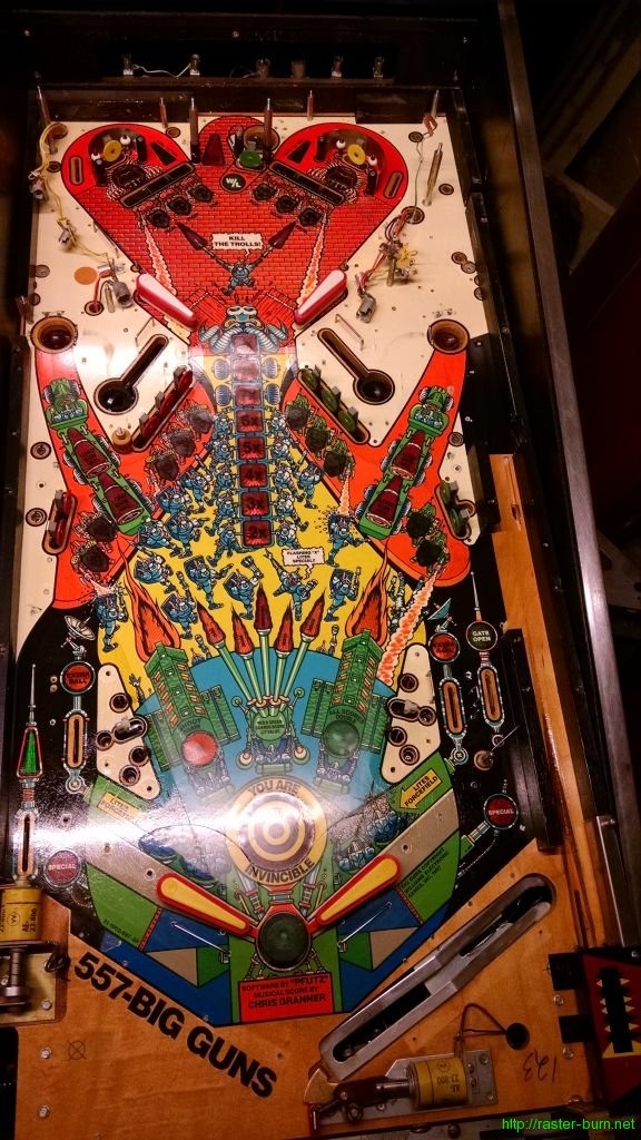
From this…

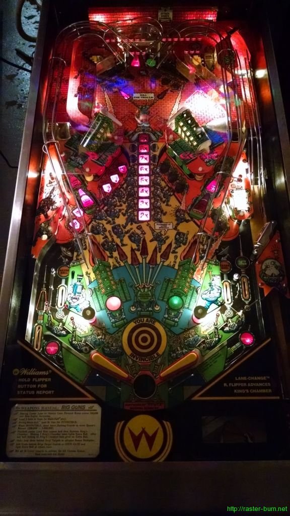
…to this…

…took about 3.5 hours over two sessions. Or, to put it in relative terms, about a third of the time I put into Sorcerer, and even more favorable compared to Comet… Though I can’t say exactly how much better since I didn’t keep time for that one. I’m very pleased with how streamlined my workflow is becoming. During disassembly I basically break the playfield into a 2×8 grid and work my way through each section, photograph it, remove parts in logical (to me, at least) groupings, and bag and label each subassembly.

I found that the most time consuming part of reassembly on the previous two tables was filling in the blanks where I hadn’t done enough documentation during teardown. Being extra methodical with breaking this one down saved me a ton of time in recomposing it, despite the significant increase in complexity from System 9 pins like Comet and Sorcerer to the more feature laden System 11 based Big Guns.

Given there are 2-4 layers of parts to remove to get to any given bulb, I wasn’t thrilled at the prospect of having to tear things down to get to short-lived incandescents, so I decided to go the LED route. I used Pinballbulbs.com non-ghosting LEDs in warm white for the #44 general illumination and cool white for the #89 flasher bulbs on the top of the playfield and in the area behind the ‘wall’ at the back.

I think the results look pretty nice. The photo makes it look like a lot of the plastics are blown out by the brightness of the LED bulbs but in person they have a nice bright, even light behind them that shows off the art and lights up the playfield nicely without being overpowering. After seeing how the top of the playfield looks I’m going to go forward with replacing the lamps under the inserts on the bottom of the playfield, and replace the lamps in the backbox as well. The previous owner installed a color ‘coordinated’ LED kit in the backbox and it makes the art look really bad, since the color of the LEDs completely overpowers the translite’s coloration.

Now that Big Guns is back together I’m going to swap it in for Sorcerer at the office and bring that one into the shop for some MPU diagnosis… After having several hundred balls played through it without a hiccup during a party the company hosted I turned it on the day after and it was resetting randomly during gameplay. Poking around (very literally) narrowed the issue down to a bad connection or flaky component in the lower right corner of the MPU board, but tracing it further than that is more than I want to do with the limited tools I have at the office.

If you’re interested in seeing what the disassembly process looks like (or have one of these things you’re trying to piece together yourself), see the gallery below for all of the reference photos I took while tearing this thing down: